General arrangement drawing: what a GA drawing shows and how to generate one
A general arrangement drawing, or GA drawing, shows how a product or an installation is laid out as a whole. It gives the overall size, the main parts and the points where it connects to everything around it. For equipment, it is the drawing that goes out with the quote, so the customer can check the fit before ordering. This guide covers what a GA shows and how it differs from assembly and shop drawings, then how to generate one from a configured model.

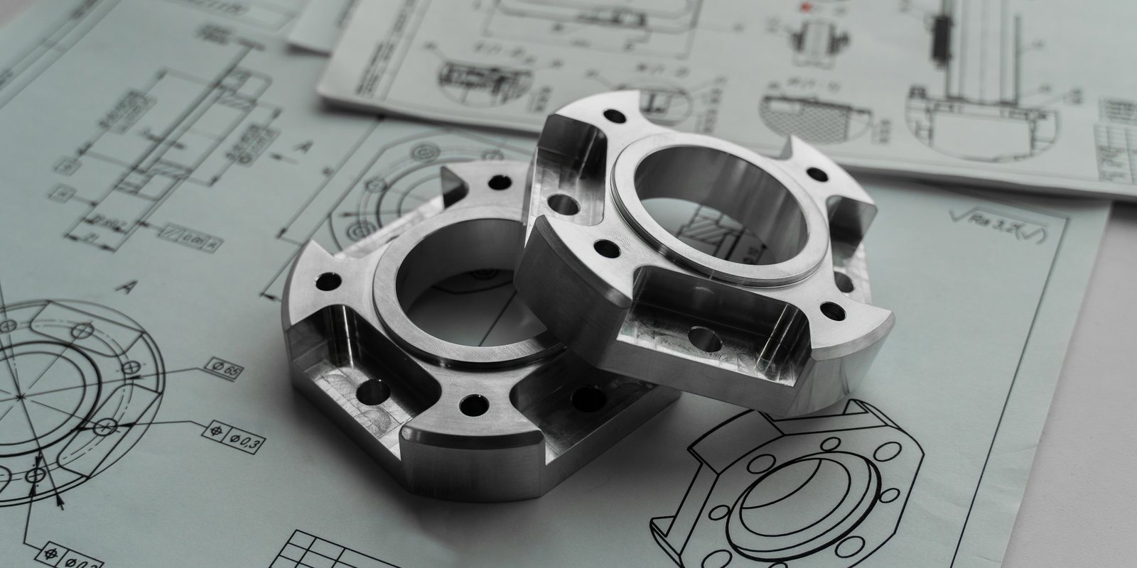
What a general arrangement drawing is
A general arrangement drawing describes the whole of something rather than its parts. It answers the questions a customer, an installer or a building engineer asks before anything is made. They want to know how big the product is and what its main parts are. They also want to know where it meets the floor, the power supply and the equipment beside it.
Tekla, the structural modelling software, describes a general arrangement drawing as a contract document that shows how a project’s structural elements are arranged. The Designing Buildings wiki describes GA drawings as showing the overall composition of an object, such as a building.
The abbreviation is GA, and you will also see GA drawing, GAD and arrangement drawing. In structural steel and construction, a GA shows how members and assemblies sit in the building. In equipment and machinery, it shows the product as delivered and how it fits the customer’s site.
What a GA drawing shows
The content varies by industry. A GA drawing for a piece of equipment usually carries the items in this table. Each one answers a question the customer would otherwise ask by email.
| Element | What the customer reads from it |
|---|---|
| Main views | The product from the front, the side and the top, often with an isometric view for orientation. |
| Overall dimensions | Length, width and height, and whether the product fits the space and the doors it has to pass through. |
| Interfaces | Where power and data connect, where product enters and leaves, and where the next machine meets this one. |
| Anchors and supports | The footprint, the hole pattern for anchoring and the load each support puts on the floor. |
| Clearances | The space needed around the product for access, maintenance and opening guards or doors. |
| Weight and lifting points | The shipping and operating weight, and where to lift the product during installation. |
| Major components | The main assemblies, called out with balloons and listed in a short parts list. |
| Notes and title block | Finish, applicable standards, exclusions, the drawing number, the revision and who approved it. |
A GA leaves out what the customer does not need. It carries no tolerances for individual parts, no weld symbols and no machining notes. Those belong on the drawings your own shop builds from.
GA drawing vs assembly drawing vs shop drawing
A GA drawing is often confused with the drawings that follow it. They usually come from the same model, but each one answers a different question for a different reader.
| Drawing | Who reads it | What it holds | When it is made |
|---|---|---|---|
| General arrangement | The customer, the installer and the building engineer | The overall layout, size, interfaces, weights and clearances | At the quote, then revised when the order is placed |
| Assembly drawing | The assemblers in your own shop | How parts and sub-assemblies go together, with a complete parts list | After the order, once the design is released |
| Detail drawing | The machinist or fabricator making one part | Every dimension, tolerance, material and finish of that part | After the order, before the part is made |
| Shop drawing | The fabricator, and in construction the engineer who approves it | How a fabricated item will be built and installed, prepared by the supplier | Before fabrication starts |
The distinction between a GA and an assembly drawing matters most in practice. The assembly drawing is written for your own people, who need to build the product. The GA is written for someone outside your plant who needs to accept it, install it and connect it.
A general arrangement drawing example
Here is what the GA for a configured conveyor section would carry. The example is generic, and almost every item on it changes with the options the customer chose.
- A side view with the overall length, the belt height above the floor and the drive position.
- A top view with the belt width, the frame width and the position of each support leg.
- An end view with the guarding, the side rail height and the location of the electrical box.
- The anchor hole positions, and the load at each support.
- The drive and the electrical connection point, called out by balloon.
- A parts list naming the main assemblies, and a title block with the configuration number and revision.
Two orders with different lengths need two different GAs, and that is where the drafting time goes. Each new GA is mostly the previous one with new numbers. That makes it a good candidate to generate from the model instead of redrawing it.
Why the GA goes out with the quote
For equipment, the customer cannot approve a price without knowing the product fits. The GA lets their engineer check the footprint, the heights and the connection points against their building and their line. It also fixes the scope, because the price covers what the drawing shows.
That makes the GA part of the quote package, along with the price, the lead time and the terms. When the customer changes the length or the drive position, the price and the GA have to change together. A quote that carries an old drawing invites a dispute at delivery.
It also puts the drafter on the critical path of every quote. When one person redraws each GA from the last similar job, the quotes wait for that person. CPQ for manufacturing covers how the price and the drawing can come out of the same configuration.
Revisions and approval
Treat the GA like any other controlled document. Every version that leaves the building gets a revision letter, a date and the name of the person who approved it. When the customer marks it up, the change goes back into the configuration rather than into a one-off edit of the drawing. That keeps the price and the drawing in step.
Many customers return the GA signed as approved for manufacture. Keep that signed copy with the order, because it records exactly what they accepted.
How to generate a GA drawing from the configured model
A GA can be generated once three pieces exist. Rules turn the order’s options into dimensions and parts. A parametric model takes those dimensions. A drawing template is linked to that model, so its views and dimensions follow the model when it changes.
Design automation tools already work this way, with rules written in their own editors. DriveWorks generates order-specific SOLIDWORKS models, assemblies, drawings and bills of materials from rules. Tacton offers design automation for SOLIDWORKS, Autodesk Inventor and PTC Creo. Autodesk lists automated drawings among the AI features in Fusion, generating 2D manufacturing drawings from a 3D model.
What AI changes is where the rules come from and who reads the request. A model can read the Excel builder into rules, read an emailed request into options and draft the notes and the cover letter. It does not set a dimension. Every number on the drawing comes from the rules and the CAD model, which a person can open and check. AI CAD covers the tools that try to generate geometry from a prompt instead, and why a drawing someone builds from needs rules behind it.
Checking a generated GA drawing
A generated drawing still gets checked. Write down the list your senior drafter already uses, so it applies to every drawing the same way:
- The overall dimensions match the configuration, and each one is driven by the model rather than typed in as text.
- Every interface the customer needs is shown, and dimensioned from a point they can measure on site.
- The parts list matches the bill of materials the configurator produced.
- The title block carries the right customer, configuration number, revision and date.
- The notes on finish, standards and exclusions match the scope of the quote.
- The files match what the customer asked for, often a PDF of the drawing and a STEP file of the model.
Run the list on ten past orders before trusting it on new ones. Generate each GA from the old configuration and compare it with the drawing that went out. Each difference is either a rule to fix or a manual change that should become a rule.
Customers sometimes send their own STEP file to show where your equipment has to fit. You can open it in the browser with the free STEP file viewer, without a CAD seat. ThriveAI builds the generated GA as part of a quote package that a named person approves, as the AI CPQ offer describes.